Tag Archives: ccent

CCNA Data Center – Introducing Overlay Transport Virtualization (OTV)

Overlay Transport Virtualization

OTV is one of the many exciting new protocols we get to study in the CCNA Data Center. However, what the heck is it? What problems does it address? Let’s tackle that in this post.

Today, we often locate data centers a far distance from each other, and we might often need to make them look like they are the same structure from a Layer 2 perspective. For example, two virtualized services might expect to be able to find each other at Layer 2. In the past, solutions like EoMPLS (Ethernet over MPLS) and dark fiber were attempted. Unfortunately, these solutions present many issues of their own.

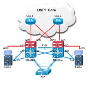
Enter the OTV solution. This technology does what we like to call MAC address routing. A control plane protocol exchanges MAC address reachability information between the data centers.

OTV does not require additional configuration to support multihoming and spanning tree protocol domain independence. OTV ensures that if there is an STP failure in one data center, it does not affect the other data center.

One of my favorite facets of OTV is the fact that the routing protocol in use in the control plane to make OTV function is IS-IS! This standards-based, OSPF competitor is making a real comeback. It was selected because it is a standard-based protocol, originally designed with the capability of carrying MAC address information in the TLV. Sadly, OTV does not get the credit in naming it deserves as most call the control plane protocol of OTV simply the OTV Protocol.

Interestingly, most deployments require no specific knowledge of IS-IS configuration (or even theory) since the routing protocol works its magic automatically as OTV is configured on your devices.

I will be back with other follow up posts on this technology including a look at terminology and configuration.

If you want to peek ahead and have some fun – check out the CBT Nugget below from yours truly!

Check out my very latest CCNA Data Center training (Late 2018) at CBT Nuggets:

https://www.cbtnuggets.com/it-training/cisco-ccna-data-center-200-155
CCNA Data Center – Fibre Channel Port Types

Fibre Channel Port Types

This post ensures you recall the standard Fibre Channel port types. This is important information to master since it is critical for understanding the FCoE protocol that we are tested on in CCNA Data Center. This testing is in addition to the questions we might face on Fibre Channel itself. In fact, let’s face it, Cisco could easily pull from the information we have here in this post!

This is another great area where you want to use Flash Cards in your prep most likely. It might also help you to draw your own diagrams after studying some that you can find via Google. Well, with no further delay – here are the Port Types that we should master:

  • Expansion PortE Port – it connects to another E port in order to form an interswitch link (ISL) between two switches.
  • Fabric PortF Port – it connects to a peripheral device (like a host or disk). Note that the device it connects to has an N port.
  • Fabric Loop PortFL Port – these port types for the arbitrated loop have faded from our networks due to the legacy nature of Fibre Channel hubs. You might still encounter arbitrated loops used inside storage architectures of storage products. The FL port connects to one or more NL ports.
  • Trunking Expansion PortTE Port – these ports connect to other TE ports to create an extended ISL connection. This is used to do things like VSANs and advanced QoS.
  • Node-proxy PortNP Port – an NP Port is a port on a device that is in N-Port Virtualization (NPV) mode and connects to the core switch via an F Port. NP Ports function like node ports (N Ports) but in addition to providing N Port operations, they also function as proxies for multiple physical N Ports.
  • Trunking Fabric PortTF Port – in TF Port mode, an interface functions as a trunking expansion port. This interface connects to another trunking node port (TN Port) or trunking node-proxy port (TNP Port) to create a link between a core switch and an NPV switch or a host bus adapter (HBA) to carry tagged frames. TF Ports are specific to Cisco MDS 9000 Series switches and expand the functionality of F Ports to support VSAN trunking. In TF Port mode, all frames are transmitted in the EISL frame format, which contains VSAN information.
  • TNP Port – in TNP Port mode, an interface functions as a trunking expansion port. This interface connects to a TF Port to create a link to a core N Port ID Virtualization (NPIV) switch from an NPV switch to carry tagged frames.
  • Switched Port Analyzer (SPAN) Destination PortSD Port – in SD Port mode, an interface functions as a SPAN. The SPAN feature is specific to Cisco MDS 9000 Series switches. An SD Port monitors network traffic that passes through a Fibre Channel interface. Monitoring is performed using a standard Fibre Channel analyzer (or a similar Switch Probe) that is attached to the SD Port. SD Ports cannot receive frames and transmit only a copy of the source traffic. This feature is nonintrusive and does not affect switching of network traffic for any SPAN source port.
  • SPAN Tunnel PortST Port – in ST Port mode, an interface functions as an entry-point port in the source switch for the Remote SPAN (RSPAN) Fibre Channel tunnel. ST Port mode and the RSPAN feature are specific to Cisco MDS 9000 Series switches. When a port is configured as an ST Port, it cannot be attached to any device and therefore cannot be used for normal Fibre Channel traffic.
  • Fx Port – an interface that is configured as an Fx Port can operate in either F or FL Port mode. Fx Port mode is determined during interface initialization, depending on the attached N or NL Port.
  • Bridge portB Port – whereas E Ports typically interconnect Fibre Channel switches, some SAN extender devices implement a B Port model to connect geographically dispersed fabrics. This model uses B Ports that are as described in the T11 Standard Fibre Channel Backbone 2 (FC-BB-2).
  • G-PortGeneric_Port – modern Fibre Channel switches configure their ports automatically. Such ports are called G-Ports. If, for example, a Fibre Channel switch is connected to a further Fibre Channel switch via a G-Port, the G-Port configures itself as an E-Port.
  • Auto Mode – an interface that is configured in auto mode can operate in one of the following modes: F Port, FL Port, E Port, TE Port, or TF Port, with the port mode being determined during interface initialization.