A key element of the Cisco UCS system you should understand is called the Finite State Machine (FSM). The FSM is a workflow model that is composed of the following:
- A finite number of stages (states)
- Transitions between those stages
- Operations
The current stage in an FSM is determined by past stages and the operations performed to transition between the stages. A transition from one stage to another is dependent on the success or failure of an operation.
Cisco UCS Manager uses FSM tasks that run in the Data Management Engine (DME) to manage endpoints in the Cisco UCS object model. For your CCNA Data Center studies, it is very important that you realize what types of tasks fall under this FSM workflow model. These include:
- Physical components – examples include the chassis, I/O module, and servers
- Logical components – examples include the LAN cloud and policies
- Workflows – examples include server discovery, service profile management, downloads, upgrades, and backups
The DME manages the FSM stages and transitions and instructs the Application Gateway (AG) to perform operations on the managed endpoints. Each stage can be considered to be an interaction between the DME, AG, and managed endpoint. The AGs do the real work in interacting with managed endpoints, such as the CIMC, adapter, or I/O module.
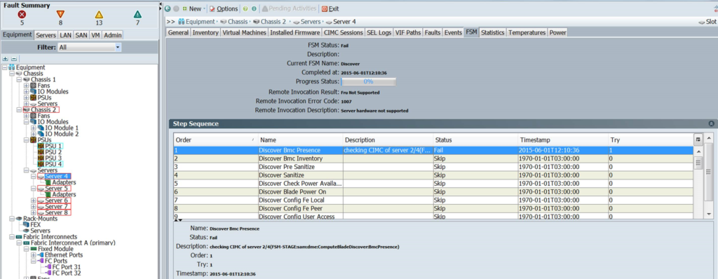
When all of the FSM stages have run successfully, Cisco UCS considers the FSM to be successful. If the FSM encounters an error or timeout at a stage, the FSM retries that stage at scheduled intervals. When the retry count has been reached for that stage, the FSM stops and Cisco UCS Manager declares the change to have failed. If an FSM task fails, Cisco UCS Manager raises faults and alarms.
Multiple FSM tasks can be associated with an endpoint. However, only one FSM task at a time can run. Additional FSM tasks for the same end point are placed in a queue and are scheduled to be run when the previous FSM task is either successfully completed or fails. You can view the FSM details for a particular endpoint to determine if a task succeeded or failed. You can also use the FSM to troubleshoot any failures.
